Case Insight
QFP solder joint fractures can reveal the loading path.
A heel-origin fracture that propagates toward the toe is a classic fatigue pattern for vibration-loaded gull-wing solder joints.
What This Case Shows
This case involved fractured solder joints on large 304-pin QFP FPGA packages after environmental vibration testing. The fracture evidence pointed to vibration fatigue rather than poor solder quality, lead-finish trouble, or a primary soldering process defect.
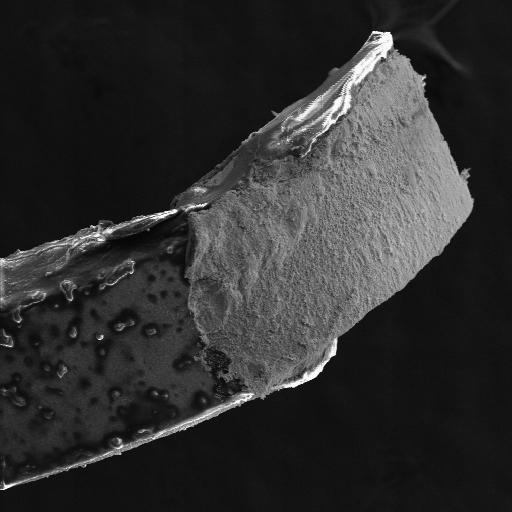
The key image shows the lead side of a fractured solder joint from QFP U44_203. The fracture originated in the heel fillet and propagated toward the toe, which is the expected high-stress path for a vibration-loaded gull-wing solder joint.
The Evidence That Matters
Multiple fractured joints on U44 and U45 showed a consistent heel-to-toe fracture pattern. That direction matters because the heel fillet is the high-stress region when gull-wing leads flex under vibration.
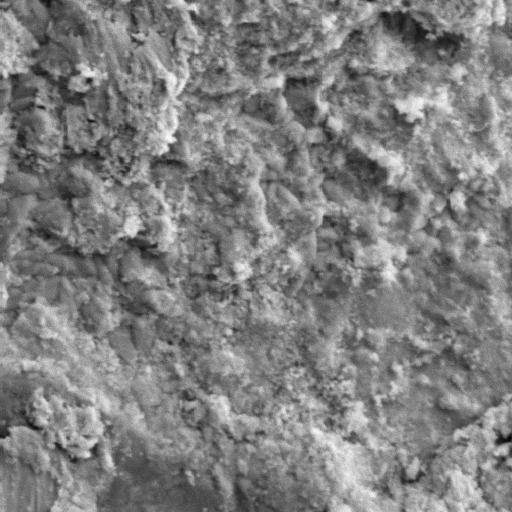
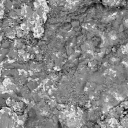
High-magnification SEM showed mixed intergranular and transgranular fracture character typical of fatigue in eutectic Sn-Pb solder. BSE imaging and EDS placed the crack path through Sn-Pb solder at or near the Cu-Sn intermetallic compound region.
Interpretation
The best-supported interpretation is vibration fatigue of gull-wing QFP solder joints. The fracture origin, propagation direction, and fracture morphology all point toward cyclic mechanical loading.
The original report found no evidence that solder quality, solder process, or component lead finish contributed to the failures. The likely drivers were the large package mass, vibration conditions that exceeded the expected envelope, or both.
A careful conclusion is:
The solder fractures were caused by vibration fatigue, with cracks originating in the heel fillet and propagating toward the toe. The evidence did not support a primary solder-quality or lead-finish cause.
Questions Engineers Usually Ask
Do non-coalesced solder balls or surface features mean non-wetting?
They are worth noting, but they should not become the root cause unless they connect directly to the fracture origin and failure sequence. In this case, the report found that the as-soldered joints met applicable requirements and found no evidence of a solder process or lead-finish issue.
Why does the heel fillet matter?
The heel fillet is where gull-wing lead geometry concentrates stress during vibration. Once a fatigue crack starts there, it can propagate toward the toe and through the side and toe fillets.
Should the fix be board stiffening or staking?
The failure analysis identifies the failure mechanism, but the corrective action depends on the mechanical system. Board stiffening may help if board bending drives lead strain. Staking or adhesive support may help if package motion or local resonance is the main driver. Either fix should be validated by strain measurement, modal review, or repeat vibration testing.
Practical Use
Use this case when QFP, gull-wing, or other leaded components fail after vibration, shock, HALT, ESS, or environmental qualification testing. It is especially useful when the engineering question is whether the evidence indicates solder process quality or vibration-driven strain.
Recommended Next Actions
- Map fractured joints by package side and pin range.
- Document whether cracks begin at the heel, toe, side fillet, or interface.
- Use SE SEM imaging for fracture topography.
- Use BSE SEM and EDS for solder phase and intermetallic context.
- Compare complete and partial fractures with neighboring intact joints.
- Review package mass, heat-sink attachment, board support, and vibration fixture conditions.
- Validate stiffening or staking changes with strain measurement or repeat vibration testing.
Focused Review
Need help separating solder quality from vibration fatigue?
Submit SEM images, EDS results, photos, and case context for a focused written interpretation of the likely mechanism and the evidence limits.